The oil and gas recovery device processes a mixture of oil and gas with air. Explosion protection is a fixed matter during the design stage, not a project that can be remedied after commissioning. The membrane method device has an advantage in structure - the membrane components are non-porous and dense, and no open flames or static electricity accumulation occurs during operation. However, the booster pump, vacuum pump, electric control cabinet, and pipeline flanges in the device are still in a flammable gas environment, so explosion protection design cannot be omitted. This article clarifies the key points of explosion protection zoning, equipment selection, and electrostatic grounding for membrane method oil and gas recovery devices, so that new construction and renovation projects can be checked against these points during the design review stage.
How to divide explosion-proof zones
The zoning is determined based on the nature of the release source and ventilation conditions: collection pipelines, membrane units, and buffer tanks, which occasionally release during normal operation, are mainly classified as Zone 2; connection parts such as oil unloading interfaces and breather valve connections, which are frequently operated, are strictly controlled as Zone 1 locally; electric control cabinets and junction boxes are arranged in non-hazardous areas, or installed after the box body meets the required protection standards. The zoning map is finalized during the drawing phase and delivered together with the plane layout and pipeline routing. Both construction and acceptance are based on this. After the station is renovated or expanded, the zoning map should be updated simultaneously - this is also an easy-to-miss step, and inspection is often reactive.
How to determine equipment selection
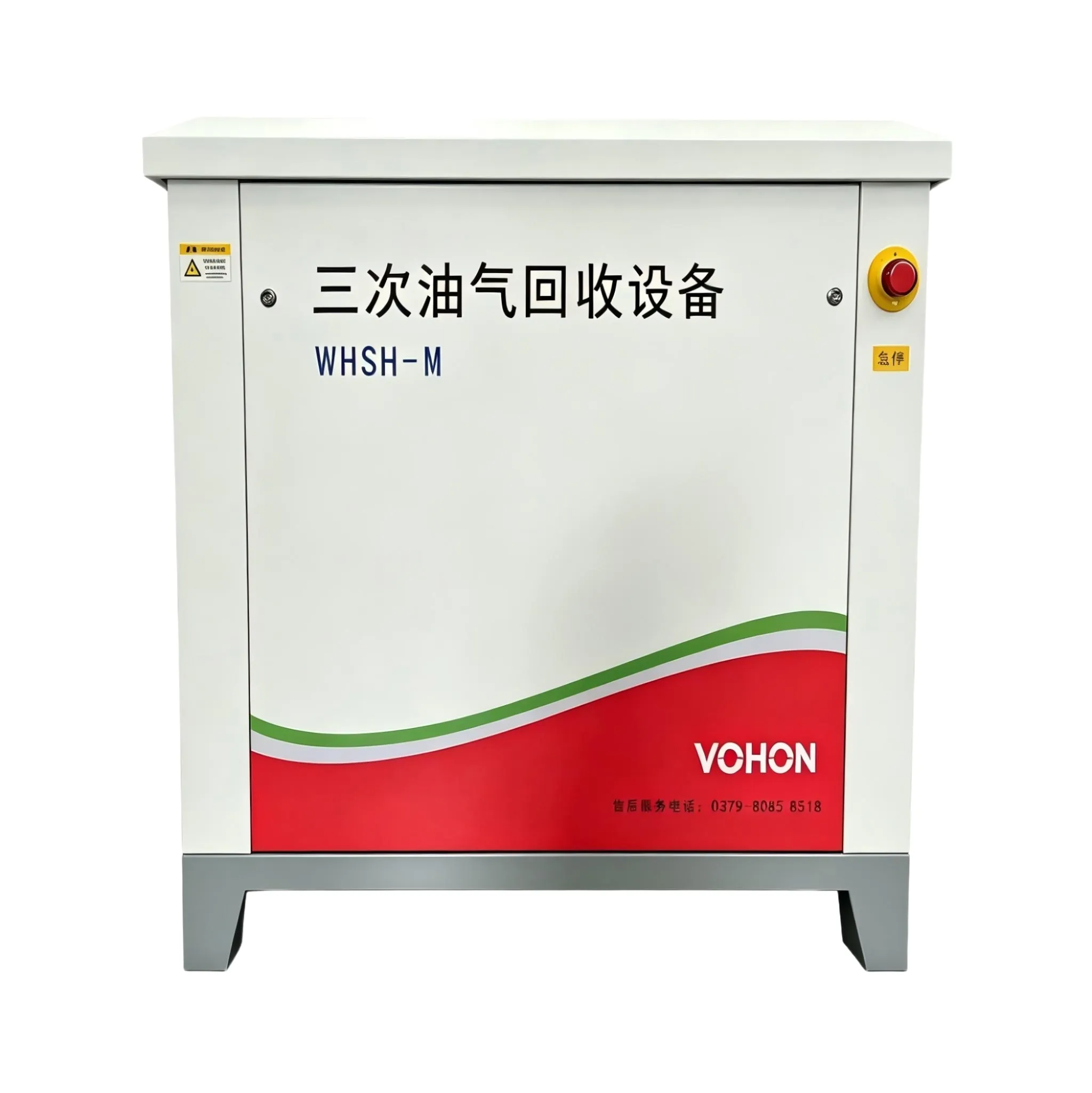
Electrical equipment within the hazardous area should be selected according to the specific area: motors and solenoid valves should be chosen as flameproof or increased safety types, while instruments should be selected as intrinsically safe types. The protection level and temperature group of the enclosure should be verified based on the characteristics of the medium - the temperature group for gasoline vapor is an input for model selection. Choosing a higher temperature group can pose hidden dangers, while choosing a lower one can increase costs. For vacuum pumps and booster pumps, the type of shaft seal should be considered: a leak-free sealing structure reduces emissions from the source, which is more practical than simply relying on shell protection. When non-standard skids are shipped as a whole, the explosion-proof documents and nameplate information should correspond to the drawings one by one, and be checked item by item upon arrival for acceptance; if parts are missing, it will take a long time to reorder on site, so this acceptance step should not be skipped.
How to manage electrostatic grounding
The flow of oil and gas within pipelines generates static electricity, and grounding is a crucial step to conduct away the electrical charges: the skid-mounted unit itself, pipeline flange bridging, and the connection points of oil unloading trucks are all integrated into the grounding network. Flange bridging tends to fail after anti-corrosion coating, so the focus during inspection should be on the contact surface. Grounding resistance is measured periodically, with test points fixed in position and numbered, and the data recorded in a logbook. The electrostatic risk during oil unloading operations is relatively high at the moment of connection. Quick connectors with bridging capabilities and the operational sequence of connecting the static electricity first and then opening the valve should be written into the operating procedures and trained to everyone involved. Merely hanging it on the wall does not suffice.
There is another aspect that is often overlooked during design reviews: explosion-proof design is not just about purchasing all the necessary explosion-proof equipment. The interfaces between equipment - such as cable entry devices, conduit seals, and blockages at the inlet of junction boxes - are often the focus of inspection. During construction disclosure, the interface practices should be included in the node diagram, and acceptance should be carried out node by node. Only then can the overall explosion-proof level be established.
Explosion-proof configuration list
| project | Design aperture | Remarks |
|---|---|---|
| Partition division | According to the release source and ventilation conditions | Finalize the drawings during the design phase |
| Regional equipment | Explosion-proof/Increased Safety/Intrinsically Safe Correspondence | Temperature group verification |
| Pump shaft seal | Priority given to leak-free sealing | Reduce release at the source |
| Grounding network | Full coverage of skid flange bridging | Test point number |
| Oil unloading docking | First, discharge static electricity, then open the valve | Individualized training on procedures |
| Interface sealing | Cable entry and conduit | The landing point of the inspection |
Acceptance and daily management
- Check and archive the qualification documents and nameplates of explosion-proof equipment one by one;
- Conduct acceptance inspection on the consistency between the zoning map and the as-built drawing, and update them after renovation and expansion;
- The grounding resistance is measured periodically, and the test point numbers are recorded in the ledger;
- The appearance of the flange crossover is inspected monthly, and retested after anti-corrosion treatment;
- For oil unloading operations, connect the static electricity first and then open the valve, and ensure that everyone is trained on the procedures;
- The explosion-proof inspection items have been incorporated into the monthly inspection checklist.
Frequently Asked Questions
Does the membrane module itself need to be explosion-proof?
The membrane module is a non-porous, dense component without electrical parts, and does not constitute an ignition source itself. The focus of explosion protection for the device lies in the pump, valve, electronic control, and wiring. The explosion zones are designated based on the overall environment of the device, rather than solely relying on the membrane components.
How to assess the zoning of the old station's renovation?
Verify the release sources according to the existing device diagram and on-site actual measurements, update the zoning diagram simultaneously after adding new interfaces for expansion and renovation, generate the rectification list based on the new zoning, and compare the consistency between the acceptance inspection and the drawings.
How often should the electrostatic grounding be tested?
Follow the prescribed cycle for implementation, and conduct an additional test after seasonal changes and anti-corrosion operations; record the test data in the ledger, and in case of abnormal trends, first inspect the contact surface, and then check the grounding electrode.
This article is compiled by Luoyang Wohong Petrochemical Equipment Co., Ltd. The company provides design and manufacturing, skid-mounted customization, installation and commissioning, as well as after-sales operation and maintenance services for three-time oil and gas recovery equipment to gas stations and oil depots. If you need on-site inspection or scheme configuration, please feel free to contact us for discussion.