In the pipelines of the three-stage oil and gas recovery device, condensate is a frequent visitor: the liquid precipitated during the recovery process flows along the pipe wall and normally flows into the condensate tank for discharge; when the discharge is not smooth, it accumulates at low points, causing instrument readings to drift and recovery volume to decrease at the least severe level, and at the most severe level, it can form a liquid blockage that blocks the gas path, causing the device to run idle when turned on. The treatment of condensate accumulation is not difficult, but it lies in timely detection and accurate location - keeping the direction of the pipeline and the location of the low points in mind, and combining with a few simple judgment methods, most accumulation problems can be dealt with before the impact expands.
What signals will be generated by accumulation
There are three signals indicating condensate accumulation: First, the pressure difference does not match the liquid level - the liquid level in the condensate tank does not rise, but the pressure difference in the pipeline continues to increase, and the liquid is mostly accumulated in the middle of the pipeline; second, the flow rate fluctuates - when the accumulated liquid is about to become a liquid blockage, the gas flow pushes the liquid away in sections, causing the flowmeter pointer to swing significantly; third, temperature stratification - there is a difference between the temperature of the liquid-filled pipeline section and the gas-phase pipeline section, and a rough judgment of the location can be made by comparing the feel. Among the three signals, pressure difference is the most reliable. It is recommended to record the normal pressure difference of each pipeline section as a benchmark table, and check for deviations. The judgment should be transformed from feeling to numbers.
How are gas blockage and liquid blockage formed
When the slope in pipeline design is insufficient, or when the support settles during use, liquid will accumulate at the low points; when the accumulation is small, it merely increases resistance, but when the accumulated liquid blocks the pipe section, liquid blockage occurs - upstream gas cannot pass through, and downstream gas cannot be extracted. Gas blockage is a different matter: in the riser, gas and liquid alternate, and the gas is blocked by the liquid column and cannot rise, manifesting as delayed suction force after the device is started. The causes of the two are different, and the treatment methods are also different: liquid blockage relies on drainage, releasing the liquid at the low points; gas blockage relies on modification, adjusting the slope and direction of the riser to allow the liquid to flow naturally.
How to conduct troubleshooting and clearance
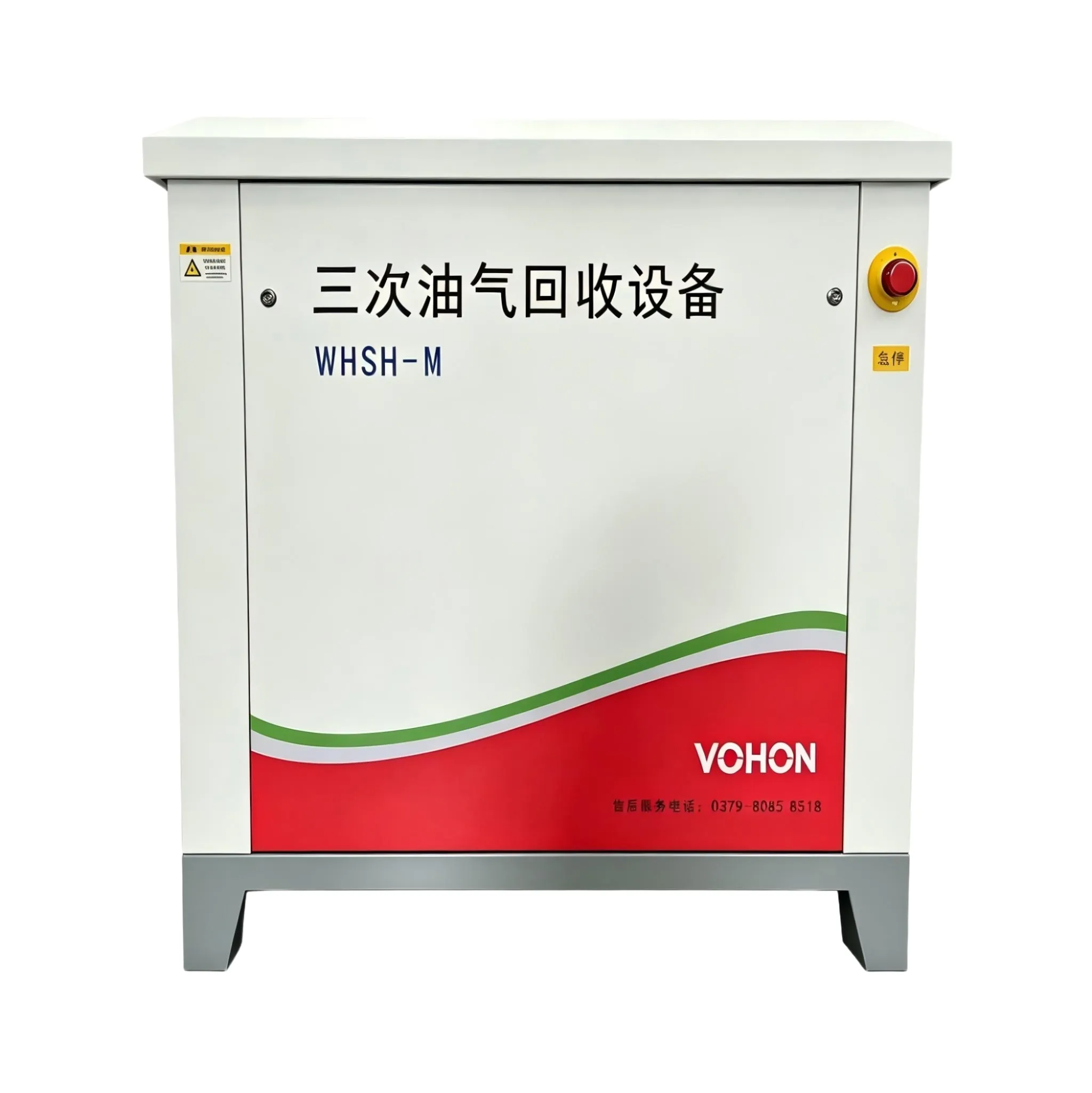
Start troubleshooting from the low points: Refer to the piping diagram and make a list of all low-point drain outlets. Open the valves one by one to drain the liquid. If no liquid is discharged from a low point, it is abnormal - most likely, the drain outlet is blocked. The methods for unblocking are prioritized based on severity: mild accumulation can be resolved by draining from the low point; if the drain outlet is blocked, use compressed air to blow back, ensuring to isolate first before blowing, and avoid blowing liquid into the wrong equipment; for large pieces of debris stuck in elbows and reducers, remove the flanges for cleaning. After unblocking, retest the pressure difference of the pipe section, and it is considered complete when it returns to the baseline value.
How to prevent repeated accumulation
| Signal/Location | basis for judgment | Processing method |
|---|---|---|
| Pipeline pressure difference | Deviating from the benchmark and continuing to rise | Check and dredge low-point emissions |
| Traffic fluctuation | The pointer swings wildly | Check the location of liquid blockage |
| Low point drain | The valve cannot be opened to release liquid | Back-blowing or dismantling flanges for cleaning |
| Riser air resistance | The suction force doesn't increase after startup | Adjust the slope and change the direction |
| Stent subsidence | Gradient reversal ponding | Annual review and adjustment of supports |
| Low temperature season | The amount of condensate increases | Increase the frequency of emissions |
Prevention is easier than dredging: Add low-point drainage outlets to pipe sections with insufficient slope, turning occasional dredging into regular drainage; adjust the frequency of drainage according to the amount of condensate in low-temperature seasons; record each drainage event in a logbook, and identify the low point with the most drainage as the focus of the next inspection. For slope changes caused by support settlement, recheck with a level ruler during annual inspection, adjust the support height in a timely manner if settlement is found, and ensure that the slope direction of the pipeline is always under control.
The steps of processing
- Refer to the pressure difference benchmark table to confirm the approximate range of the accumulated pipe section;
- List all low points within the scope according to the piping diagram and drain them one by one;
- Check the drainage port for low-point emissions that are ineffective, and perform back flushing or disassembly for cleaning;
- Re-measure the pressure difference of the pipe section and return to the baseline value to confirm that the dredging is in place;
- Record the current accumulation location and emission volume, and update the inspection priorities;
- For the assessment and modification of repeatedly accumulated pipe sections, add drainage outlets or adjust the slope.
Frequently Asked Questions
How often is it appropriate to discharge condensate?
It shall be determined based on the ledger. Initially, the liquid volume shall be discharged and recorded weekly. After several consecutive weeks, the accumulation rate at each low point can be determined, and the discharge frequency shall be set accordingly. During the low temperature season and rainy season, the frequency shall be appropriately increased, and the frequency shall be adjusted based on the actual accumulation rate.
Will the back flush blow the liquid into the recovery tank?
First, close the isolation valve before purging. Arrange the purging path separately, and close the valve leading to the tank. Before resuming the process after purging, open the low-point drain to confirm that there is no residual liquid. Following this sequence will prevent tank cross-contamination.
What is the appropriate slope for the pipeline?
Maintain continuous downgrade along the flow direction, and add drainage outlets at turning points for pipe sections where continuous downgrade is not possible. The principle of old pipeline renovation is to ensure that liquids can flow naturally to the low points, without necessarily pursuing a uniform slope value. It is satisfactory if the liquids can be drained away.
This article is compiled by Luoyang Wohong Petrochemical Equipment Co., Ltd. The company provides design and manufacturing, skid-mounted customization, installation and commissioning, as well as after-sales operation and maintenance services for three-time oil and gas recovery equipment to gas stations and oil depots. If you need on-site inspection or scheme configuration, please feel free to contact us for discussion.