In the pipelines of the tertiary oil and gas recovery system, components of the oil and gas will continuously condense into liquid form during transportation: as the temperature decreases along the pipeline and the pipe wall comes into contact with a cold surface, the condensate will flow downwards along the pipe wall. If the arrangement of condensate flow paths is not optimal, it can accumulate at low points, occupying the flow cross-section at best, and at worst, it can be carried by the airflow into areas where liquid should not enter. The layout idea can be summarized in one sentence: ensure that condensate has slopes to flow along, low points to collect, and designated locations to drain.
Condensate issues often remain hidden during acceptance inspection: the new system piping is clean, and a small amount of accumulation may not be visible, thus not affecting the inspection. After operating for one or two seasons, issues such as fluid accumulation at low points, freeze-ups in winter, and liquid carryover in fans gradually emerge. The slope and drainage point design during the layout stage determine the operational status several years later.
What determines the slope
The slope direction is determined towards the destination of the condensate: towards the recovery tank direction, towards the collection manifold direction, so as to prevent the condensate from flowing back towards the device. In terms of value selection, the gas phase pipeline generally starts at 0.3% to 0.5%, and the slope should be appropriately increased for longer pipelines and sections with larger condensate volumes. Special attention should be paid to the horizontal section before entering the device, as this section is often made very flat for the connection, making it easy for condensate to accumulate in this section.
When it is not feasible to change the slope of existing pipelines, the solution is to add low-point discharge points: keep the slope unchanged, identify the fluid accumulation points, and add discharge valves point by point. Before changing the slope, flush the pipeline with water to test its flow, so as to accurately locate the actual fluid accumulation points. Only then can the added points be targeted.
How to arrange for low emissions
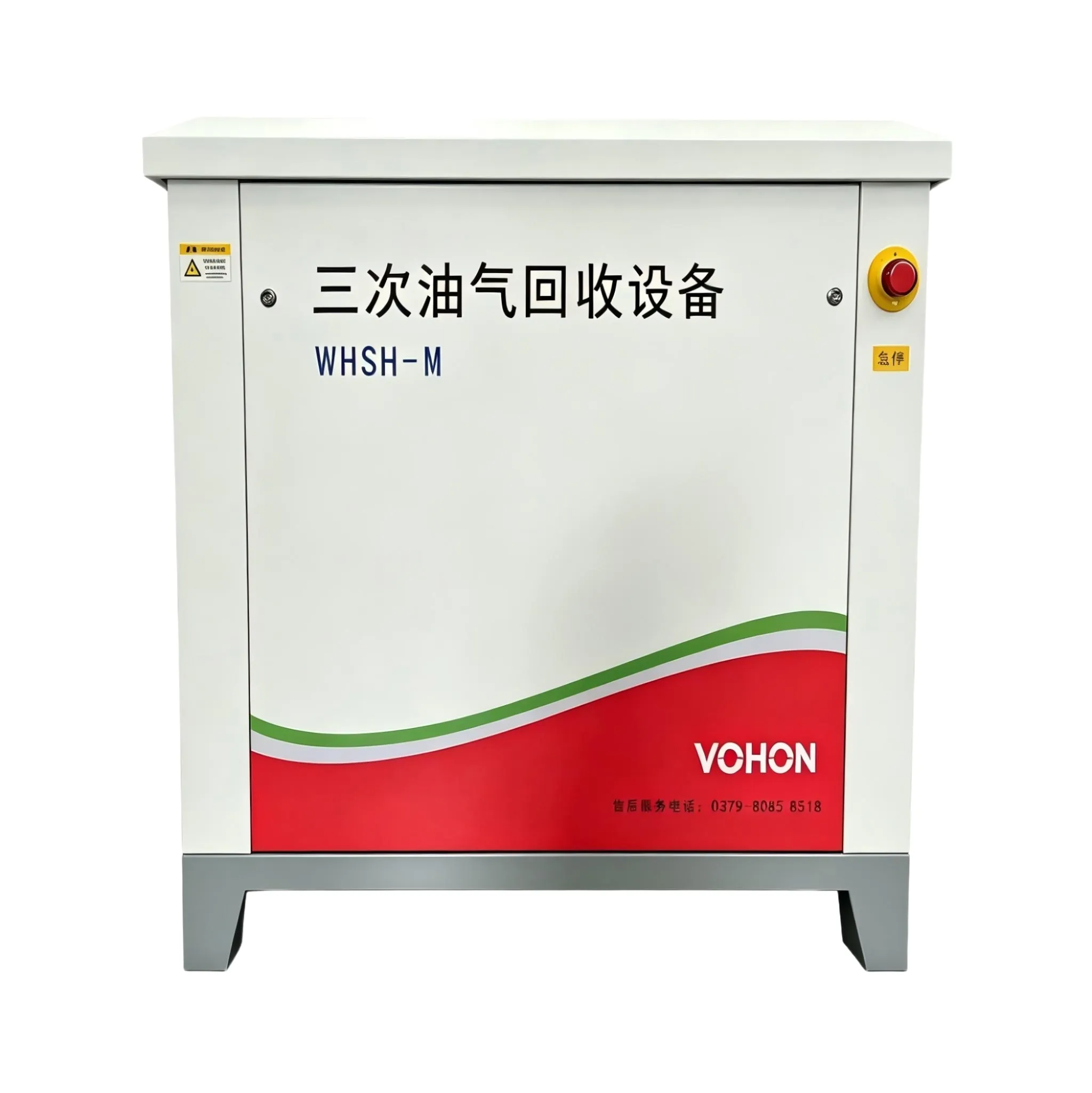
Where to set the low point depends on the actual routing of the pipeline: natural low points, areas below bends, and vertical downward sections at the end of the pipeline are all locations where condensate collects. The discharge point is equipped with three things: a discharge valve, a short pipe, and a collection interface. The discharge valve should be of the rising stem type, so the opening status can be seen; the discharge outlet should be connected to a condensate collection tank, rather than being directly open to the atmosphere - condensate contains solvent components, and opening it directly to the atmosphere is equivalent to releasing the collected oil and gas back into the atmosphere.
The location of the emission point should also take into account the operation: if the emission valve is installed at a high place that is out of reach, the implementation rate will become lower and lower, and it will eventually become a mere decoration. If it can be led to the ground, then lead it to the ground for operation.
Where does the condensate go
The condensate is categorized based on its source: condensate from the recovery section is referred to as recovery liquid and is directly metered into the recovery liquid system; condensate along the pipeline, which contains impurities, is collected in a holding tank for settling and subsequent consolidation; condensate with high water vapor content is collected separately from solvent condensate to prevent moisture from mixing with the recovery liquid and affecting its reuse.
| body part | Condensate characteristics | Key points of arrangement |
|---|---|---|
| Horizontal section along the route | Retarding, small amount | The slope is oriented towards the collection direction, with regular discharge |
| Elbow and low point | Large collection volume | Low-point drain valve with collection interface |
| Device inlet section | The interface is easy to level | Focus on checking the slope, and add drainage if necessary |
| Outlet of the recycling section | Recycled liquid | Directly enter the recovery liquid metering |
| Winter risk period | Condensate freeze blockage | Check the antifreeze and heat tracing at the emission point |
| Front duct section of fan | Risk of carrying liquid | Drain frequently at the low point before entering to protect the fan |
How to implement emission management
- On the as-built drawings, clearly indicate the slope direction and the discharge location of each low point, and compile a list of discharge points;
- The emission cycle should be clearly indicated for each emission point, and inspections should be carried out according to the checklist. Any abnormal emissions should be recorded;
- Conduct an antifreeze inspection of the discharge points of the open-air pipeline sections before winter;
- The low points before the fan and the unit inlet are listed as key points, and the emission frequency is doubled;
- After the pipeline renovation, the slope and drainage point data should be updated simultaneously.
Frequently Asked Questions
What is an appropriate periodicity for low-emission cycles?
Observe the amount of condensate. For the new system, it can be tested once a week initially, and adjustments can be made based on the amount discharged: for points where the discharge amount is consistently low, the testing period can be extended, while for points where there is rapid accumulation of condensate, the testing period should be shortened. Each point should determine its own testing period based on actual data.
Is it necessary to rework if the pipeline slope is insufficient?
Not necessarily. If low-point emissions are the issue, it can be resolved without having to modify the pipeline; only for sections with severe fluid accumulation affecting operation should local slope modification be considered. Before the modification, it is important to identify the location of the fluid accumulation, and the fewer areas that are modified, the better.
Is it okay to directly discharge the condensate into the waste oil system?
Consider the components. Condensate containing solvents should first be allowed to settle and separate in a collection tank. Recoverable components should be incorporated into the recovered liquid. If it is confirmed that there is no recovery value and the receiving requirements permit, it can be discharged to avoid affecting the operation of the oily sewage system.
This article is compiled by Luoyang Wohong Petrochemical Equipment Co., Ltd. The company provides design and manufacturing, skid-mounted customization, installation and commissioning, as well as after-sales operation and maintenance services for three-time oil and gas recovery equipment to gas stations and oil depots. If you need on-site inspection or scheme configuration, please feel free to contact us for discussion.