In the layout of the tank area, the location of the tertiary oil and gas recovery equipment is not something that can be randomly chosen after the main structure is installed. Instead, it should be determined during the tank area planning stage. Choosing the right location results in short pipelines, low resistance, and convenient maintenance; choosing a cramped location will continuously affect later operation, maintenance, and renovation. When arranging, there are three main things to focus on: the distance relationship with the storage tanks and loading/unloading areas, the reservation of maintenance operation space, and coordination with safety facilities.
Several relationships to prioritize in arrangement
Firstly, there is the distance relationship with the storage tank. The closer the equipment is to the storage tank, the shorter the collection pipeline, the less the frictional resistance along the way, and the less chance of fluid accumulation at low points; however, being too close is constrained by maintenance space and safety distances. In practical layouts, a compromise is often adopted: the equipment is arranged close to the outside of the tank area cofferdam or on one side of the tank area, and the pipeline enters the tank area by the shortest path, while leaving a maintenance surface. The distance and direction are ultimately subject to the design documents. Different tank areas have different conditions, so there is no universally applicable answer.
Next is the connection with the loading and unloading area. The loading and unloading operation areas of the oil depot are important sources of oil and gas collection. The equipment should be positioned so that the collection pipelines from the loading and unloading area are as straight as possible, avoiding excessive detours and undulations. Pipelines with many undulations are prone to fluid accumulation, which, if not handled properly, can cause resistance fluctuations.
Six steps for arranging and verifying
- Determine the collection sources: identify which storage tanks and loading/unloading areas should be connected to the recycling system, and map out the collection scope;
- Preliminary selection of equipment location: Circle two or three candidate locations on the tank farm map, taking into account both pipeline length and site conditions;
- Check spacing requirements: Verify the spacing between equipment and storage tanks, open flame locations, and roads against the design documents and local safety requirements one by one;
- Reserved maintenance space: Operation surfaces for opening doors, core extraction, and component replacement should be reserved around the equipment, rather than just leaving installation positions;
- Planning pipeline routing: Determine the slope direction and low-point discharge location, avoiding U-shaped undulations and excessive bends;
- Re-check electrical and foundation: Confirm the power supply introduction path, equipment foundation, and ground bearing conditions.
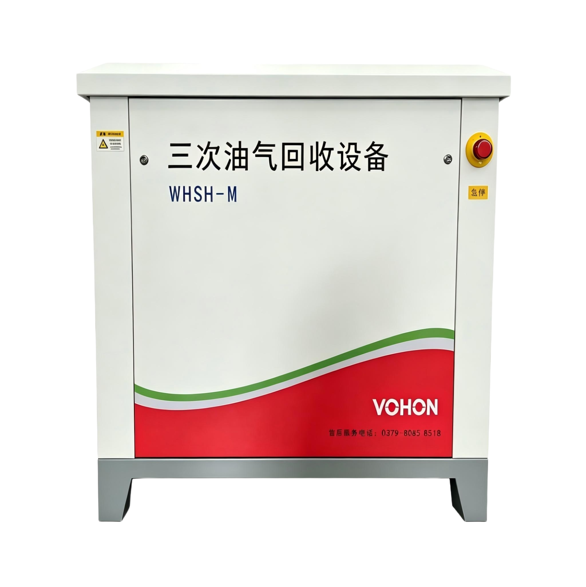
How to reserve spacing and maintenance space
The issue of spacing can be viewed from two perspectives: one is safety spacing, determined by design specifications and local regulatory requirements. Before arrangement, applicable provisions should be listed and checked item by item, and it cannot be set based on intuition; the other is maintenance spacing, which falls under the category of user experience. Whether the equipment door can be fully opened, whether the heat exchange components can be pulled out, and where the valve handwheel is located for easy operation are all easily overlooked on the drawings, and only become apparent on-site when the space is found to be limited.
The recommended practice is to draw the maintenance envelope lines of the equipment on the layout diagram, which represents the space occupied by personnel and components during normal maintenance of the equipment. Check whether this space, along with the equipment itself, conflicts with surrounding structures. After drawing these lines, many positions that seem to be feasible will be eliminated, and the remaining ones are truly usable.
Handling of pipeline routing and slope orientation
It is recommended to maintain a continuous slope direction for the collection pipeline, with liquid collection and discharge points set at the low points of the slope to avoid the occurrence of stagnant areas in the middle of the pipeline. The elevation difference between the inlet and outlet of the equipment should be calculated in advance: the inlet pipeline generally slopes towards the collection direction, while the exhaust and discharge pipelines have their respective directions. These details should be determined during the layout stage, which is much better than improvising on-site during installation.
| Layout elements | mainly consider | Handling suggestions |
|---|---|---|
| Distance from storage tank | Pipeline length, resistance, and low-point fluid accumulation | Arrange nearby, with the shortest pipeline route leading into the tank area |
| Connect with the loading and unloading area | The collection pipeline should be straight and smooth, avoiding undulations | Re-plan the route with excessive detours and undulations |
| Safety clearance | Design specifications and local regulatory requirements | Make a list and check each item, don't rely on instinct |
| Maintenance space | Open the door, extract the core, and replace the operating surface | Check together with the maintenance envelope line drawn on the diagram |
| Pipe slope direction | Continuous slope orientation, low point liquid collection and drainage | During the layout stage, determine the slope orientation to avoid U-shaped undulations |
| Electrical and Foundation | Explosion-proof requirements, power supply path, load capacity | Confirm during the design phase, don't leave it to be improvised on-site |
Coordination with safety facilities
The layout of equipment must also be coordinated with the existing safety facilities in the tank area: grounding and lightning protection practices must be implemented according to design requirements. It is necessary to confirm during the design phase where the equipment is located within the fire compartment, whether the fire escape routes are occupied, and whether the selection of electrical equipment meets the explosion-proof requirements of the area. Especially for the electrical part, the explosion-proof requirements may vary in different areas within the tank area, and both the equipment and cable laying paths must fall within the allowed range.
Special considerations during installation in the tank camp area
Installing equipment in the existing tank area imposes an additional constraint compared to building a new tank area: construction must not affect normal oil receiving and dispatching operations. When arranging, consideration should be given to construction access, lifting positions, and temporary land occupation, and locations with minimal impact on operations should be selected as much as possible. Pipeline connections should utilize planned downtime windows, with access points designed in advance to avoid prolonged temporary hot work. For such renovation layout plans, it is recommended to schedule them together with the operation plan, first determining the downtime windows, and then reversely arranging the construction steps.
Frequently Asked Questions
Is it better for the equipment to be closer to the storage tank?
不是。近了管路短是优点,但安全间距、检修空间、施工条件都要一并满足。常见做法是紧邻罐区一侧或围堰外布置,兼顾管路长度与各项要求,具体以设计文件核对结果为准。
What is the most likely to be overlooked during the setup phase?
Maintenance space. According to the drawings, the equipment can be placed within the designated space. However, in reality, additional space is required for opening doors, extracting cores, and replacing parts. Without drawing the maintenance envelope, it is often only discovered during the first major maintenance that the space is insufficient. Simulating maintenance actions during layout can help eliminate most issues in advance.
What should be the most important consideration when installing equipment in the tank area?
Conflicts between construction and regular operations. First, determine the downtime windows and lifting pathways, then reverse the construction steps. Design the pipeline access points in advance to avoid prolonged temporary hot work. When selecting locations, also consider setting aside temporary land for construction, rather than only focusing on permanent conditions.
This article is compiled by Luoyang Wohong Petrochemical Equipment Co., Ltd. The company provides design and manufacturing, skid-mounted customization, installation and commissioning, as well as after-sales operation and maintenance services for three-time oil and gas recovery equipment to gas stations and oil depots. If you need on-site inspection or scheme configuration, please feel free to contact us for discussion.